- 您现在的位置:买卖IC网 > Sheet目录1001 > PR3BMF51NSKF (Sharp Microelectronics)RELAY SSR 10MA 240V 1.2A 8-DIP
�� �
�
�PR3BMF51NSKF� Series�
�■� Design� Considerations�
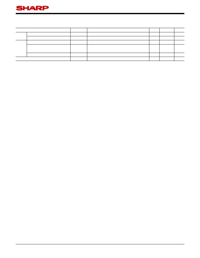
�●� Recommended� Operating� Conditions�
�Parameter�
�Symbol�
�Condition�
�MIN.�
�MAX.�
�Unit�
�Input�
�Input� signal� current� at� ON� state�
�Input� signal� current� at� OFF� state�
�I� F� (ON)�
�I� F� (OFF)�
�?�
�?�
�20�
�0�
�25�
�0.1�
�mA�
�mA�
�Load� supply� voltage�
�Output� Load� supply� current�
�Frequency�
�Operating� temperature�
�V� OUT� (rms)�
�I� OUT� (rms)�
�f�
�T� opr�
�?�
�Locate� snubber� circuit� between� output� terminals�
�(Cs� =� 0.022� μ� F,� Rs� =� 47� Ω� )�
�?�
�?�
�?�
�?�
�50�
�?� 20�
�240�
�I� T� (rms)�
�80%(*)�
�60�
�80�
�V�
�A�
�Hz�
�?� C�
�(*)� See� Fig.2� about� derating� curve� (I� T� (rms)� vs.� ambient� temperature).�
�●� Degradation�
�In� order� for� the� SSR� to� turn� off,� the� triggering� current� (I� F� )� must� be� 0.1mA� or� less�
�In� phase� control� applications� or� where� the� SSR� is� being� by� a� pulse� signal,� please� ensure� that� the� pulse� width�
�is� a� minimum� of� 1ms.�
�When� the� input� current� (I� F� )� is� below� 0.1mA,� the� output� Triac� will� be� in� the� open� circuit� mode.� However,� if� the�
�voltage� across� the� Triac,� V� D� ,� increases� faster� than� rated� dV/dt,� the� Triac� may� turn� on.� To� avoid� this� situa-�
�tion,� please� incorporate� a� snubber� circuit.� Due� to� the� many� different� types� of� load� that� can� be� driven,� we� can�
�merely� recommend� some� circuit� values� to� start� with� :� Cs� =� 0.022� μ� F� and� Rs� =� 47� Ω� .� The� operation� of� the� SSR�
�and� snubber� circuit� should� be� tested� and� if� unintentional� switching� occurs,� please� adjust� the� snubber� circuit�
�component� values� accordingly�
�When� making� the� transition� from� On� to� Off� state,� a� snubber� circuit� should� be� used� ensure� that� sudden� drops�
�in� current� are� not� accompanied� by� large� instantaneous� changes� in� voltage� across� the� Triac.�
�This� fast� change� in� voltage� is� brought� about� by� the� phase� difference� between� current� and� voltage.�
�Primarily,� this� is� experienced� in� driving� loads� which� are� inductive� such� as� motors� and� solenods.�
�Following� the� procedure� outlined� above� should� provide� suf� ?� cient� results.�
�Any� snubber� or� Varistor� used� for� the� above� mentioned� scenarios� should� be� located� as� close� to� the� main� out-�
�put� triac� as� possible.�
�All� pins� shall� be� used� by� soldering� on� the� board.� (Socket� and� others� shall� not� be� used.)�
�●� Degradation�
�In� general,� the� emission� of� the� IRED� used� in� SSR� will� degrade� over� time.�
�In� the� case� where� long� term� operation� and� /� or� constant� extreme� temperature� ?� uctuations� will� be� applied� to�
�the� devices,� please� allow� for� a� worst� case� scenario� of� 50%� degradation� over� 5years.�
�Therefore� in� order� to� maintain� proper� operation,� a� design� implementing� these� SSRs� should� provide� at� least�
�twice� the� minimum� required� triggering� current� from� initial� operation.�
�Sheet� No.:� D4-A03801EN�
�8�
�发布紧急采购,3分钟左右您将得到回复。
相关PDF资料
PRDA-11AJA-120
RELAY GEN PURPOSE DPDT 20A 120V
PRGD48150-10
RELAY SSR DC 480V RANDOM PNL MNT
PS11
GASKET 3.63 X 2.27 INCH
PS1201
SWITCH OPT ISOL 400V 8-SIP
PS13
GASKET FOR BOX 131 132 133
PS15
GASKET 5.63 X 3.25 INCH
PS17
GASKET 6.876 X 4.876"
PS19
GASKET 6.34 X 9.5"
相关代理商/技术参数
PR3BMF51NSKFC
制造商:Sharp Microelectronics Corporation 功能描述:DIP8 SSR, 10MA IFT, 600V, 900MA, NON ZC, SLEEVE - Rail/Tube
PR3BMF51NSZF
功能描述:固态继电器-PCB安装 SSR 10mA Ift 600V 1.2A nonZC VDE Sleve RoHS:否 制造商:Omron Electronics 控制电压范围: 负载电压额定值:40 V 负载电流额定值:120 mA 触点形式:1 Form A (SPST-NO) 输出设备:MOSFET 封装 / 箱体:USOP-4 安装风格:SMD/SMT
PR3-BP
制造商:Eiko Ltd 功能描述:
PR3-BSC1/2X21
制造商:Phoenix Contact 功能描述:RELAYS SOCKET PR3, 2 PDT OCT
PR3-BSC1/3X21
制造商:Phoenix Contact 功能描述:RELAYS SOCKET PR3, 3 PDT OCT
PR3DC
制造商:MTRONPTI 制造商全称:MTRONPTI 功能描述:Surface Mount Crystals 3.5 x 6.0 x 1.2 mm
PR3DCS
制造商:MTRONPTI 制造商全称:MTRONPTI 功能描述:Surface Mount Crystals 3.5 x 6.0 x 1.2 mm
PR3DCXX
制造商:MTRONPTI 制造商全称:MTRONPTI 功能描述:Surface Mount Crystals 3.5 x 6.0 x 1.2 mm